Category Archives: Test and Measurement

Instrumentation for testing and measurement electronic instruments and design.

It’s All in the Tool

Please Share

TRAVELLING BACK IN TIME

So there I was in front of the kitchen sink, scrubbing this pot that had at least eight years of grime stuck to it, having realized that I don’t want to keep serving Chicken Cacciatore left over from January 2013 to my family. Nor that delicious pot roast in wine sauce that I concocted in March 2012. I mean, both beef and wine do age well, but we’re talking health hazards here – not epicurean tastes.
So, sighing with muscle fatigue, regretting that I had stopped popping in to the neighborhood gym park some time ago, and realizing that the only iron I was pumping these days was beneath the enamel of the above-mentioned pot, I opted for a coffee break, using my left hand to pour (my right arm having ceased to function normally after its scrubbing aerobics), and decided to rest for a few minutes and ponder the tackling of this task.

coffeeCoffee always inspires! I remembered! The green baize scrubby thingy works wonders! Well, not exactly baize – more like a rough green plasticy sheet that feels gentler than sandpaper but works in the same way. After a thorough search for a piece of the green wonder (the coffee gave me the energy to do this), I found some of this treasure in the drawer at the bottom of a kitchen closet that only opens if all the other doors in the room are closed (Don’t even ask!). A few minutes inside my pot, after taking another rest to recover from the drawer/closet battle, and I could view my own reflection inside my suddenly-like-new pot!

DON’T LET THE EQUIPMENT BEAT YOU! YOU CAN DO THIS!

This ultimately successful experience reminded me that winning battles with equipment is all in the tool! It threw me back to my technician days at Bull HN Information Systems. H = Honeywell, and N = NEC. If you are too young to have heard of Groupe Bull (pronounced Bee-yool in France, home of the company’s corporate headquarters) in their Honeywell days, here’s a link to a little history about Honeywell and it’s relationship with Bull.

Don’t Let The Equipment Beat You! You Can Do This! Click To Tweet

A BRAND NEW & PROUD ELECTRONICS ENGINEERING TECHNICIAN

Proud to have graduated as an electronics engineering technician from Seneca College, Toronto, I arrived at my first job in 1991 – at Bull’s Component Repair shop in Scarborough, Ontario, eager to try out my new troubleshooting skills with a DMM and scope. My analytical skills knew no bounds. Really, all you need to know to succeed in this work are a few logic gate specs and some sort of expectations about what should be showing up on those pins: 5 V, maybe 3.3 V, 0 V. Some interesting waveforms on the screen. Right?

Wrong!

INFORMATIVE REPAIR REQUISITION SLIPS

So, first things first. Read the complaint written on the Repair Requisition slip. These can be very informative.
Like this one:
“Dead”.

A DEAD DUMB TERMINAL?!

That’s quite useful information. Usually it produces the avoidance response. Avoid powering up the instrument. Avoid calling up the customer to enquire, “So what’s actually wrong with the instrument?” Why not just avoid trying to repair it?

Not an option.

LET’S CLIMB INSIDE A MONOCHROME HONEYWELL DPS

Okay, then, let’s take a look INSIDE! My job was to repair monochrome monitors and Honeywell DPS “dumb” terminals. The terminals weren’t really dumb – but after a while, the technician (yours truly) got to feel like not such a bright spark.

In order to view the inside of the instrument, you need to open it up. How I struggled to open those boxes. On my first day on the job, I was presented with a set of tools including a power screwdriver, all shiny and red.

It had a forward/reverse button and I had two bits for it, a Phillips and a flathead. As soon as I saw it, I thought, “This is it!” This tool will take me anywhere I need to go.
As it turned out – not everywhere.

Well, after ruining the threads of almost every screw on the terminal, I bashfully, in a rather subdued voice, approached my co-workers for advice. “Help me, help me, help!”, she cried. After ensuring that there were no hunters chasing after little rabbits, (Scarborough, Ontario not really being a cottage-in-the-woods kinda place) three technicians called out in unison: “It’s All in The Tool”!

I dropped my powered screwdriver like a hot cake, and trying to be brave, dared to ask, “What tool?!”
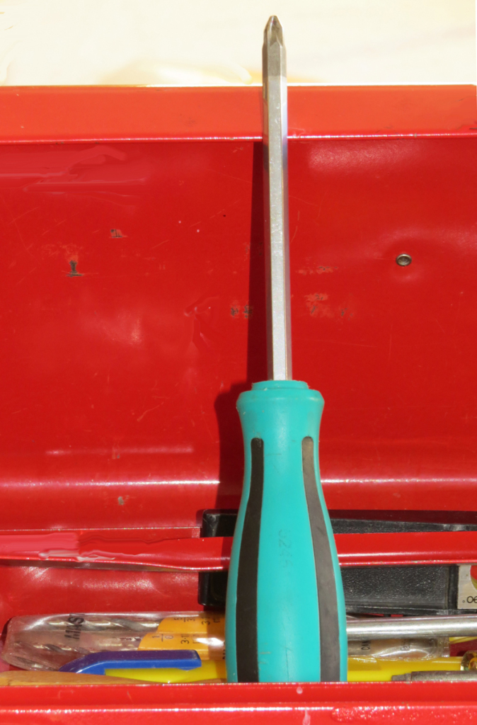
Screwdriver in toolbox

THE POWER OF PHILLIPS SCREWDRIVERS

And out they came – the powerful, yes, but not powered – the wonderful Phillips screwdrivers in all shapes, sizes, and lengths. Why did I not have one of these in my default tool set? Because they all came from Dad’s toolbox in his shed in the backyard. Note that ISO 9002 came later – we were still basking in the days of unrestricted shop conditions. They went on to explain that the power screwdrivers are fine for many tasks but not for those stubborn screws that have become embedded in plastic after years of heating. It’s guaranteed that they will want to remain right where they are. But, wait, there’s more.

THEY DID NOT TEACH ME ABOUT TORQUE IN SCHOOL

It’s not only in the tool, my new instructors cried – it’s also in the torque. Torque? And then my new-found instructors taught me how to use the tool. Choose the correct size screwdriver, position the tool correctly in the screw, apply pressure. and only then, turn. Fortunately, those were the days preceding my need to take coffee breaks each time I applied a little torque, else I would probably have been responsible for breaking some sort of Union law relating to multiple coffee breaks.

THANK YOU, BULL HN COMPONENT REPAIR IN SCARBOROUGH, ONTARIO

After that, opening equipment became a breeze. I couldn’t wait to pass on my new-found knowledge to the new wet-behind-the-ears recruits, who, like me, thought they knew it all. Now, so many years later, I would like to thank my co-workers in Bull HN Component Repair for their patience, excellent skills, and teaching abilities. I really appreciated all your assistance. Thank you!

Please Share

Basic BERT

Please Share

Not that a BERT is a basic instrument by any means. But I thought (while still in a techie mode – or would that be mood?) that I would bring you a pretty basic article on quite a complex test and measurement instrument. So grab a cup of coffee, curl up in front of your screen, and enjoy!

The Bit Error Rate Tester (BERT) is the test and measurement (T&M) device of choice when checking transmission and reception quality over telecommunications lines. These lines can be copper-to-copper, twisted pairs – such as Ethernet – coaxial cable, cellular phone (as 4GLTE) or fiber optics. Typically, all of these methods are used and they are often run through radio frequency repeaters, microwave, or satellite links. The BERT is also used to troubleshoot for problem areas, check repairs to circuits, and used to test alternate or secondary (fallback) transmission paths.

The BERT’s function is to stress test transmission lines to isolate sources of noise, jitter, intermittent connections and impedance mismatching. There are several types of stress testing. These can include maximum voltage throughput, as when sending all ones (1s), minimum voltages tests as all zeros (0s), forward error correction (ECC) and error detection and correction overhead. Alternating or pseudorandom bit streams are used to simulate typical traffic over the lines. There are far too many mathematical models and engineered algorithms to list in detail, but they are critical in the selection of the equipment.

BERTs can use a variety of multiplex and modulation modes, the more common commercial systems using some form of Phase Shift Keying (PSK) and other forms of signal concatenation. The major components of a BERT include a modulator/demodulator (“modem”) to connect the BERT to the transmission lines, a pattern generator, a clock to synchronize BERTs and establish baseline timing, an error detector, often some sort of digital analyzer to visually observe or record the devices under test, and a computer interface.

The complexity of digital transmission necessitates the use of equally complex – and generally expensive – specialized test equipment. The cost can easily be doubled when end-to-end testing from both termination points is required. As a practical rule, most tests can be run using farside or nearside loopbacks, which allow a single BERT to generate the patterns and detect errors sent back to itself via the loopback.

HP/Agilent and Tektronix BERTs dominate the field in this particular technology; however, Anritsu  has a long history of manufacturing leading edge telecommunications test and measurement equipment. More than 95% of the BERTS costing $10K and up are made by these manufacturers. Features, flexibility, and suitability to a purpose have resulted in some very expensive — $100K BERT test systems. Systems designed to a single purpose, such as DS line testing, can be much more affordable. For the field technician, companies such as Fluke and GAO handheld BERTs provide techs with rugged, durable, and portable solutions. Options such as pass-through of the original traffic can be a valuable asset when making live tests or in mission-critical applications, where the transmission line cannot be taken completely out of service.

Necessity for super-high frequency (SHF) and extremely high output (EHF) and input frequencies, USB 3.0, the most recent Windows O/S, and similar hardware and software user interfaces are all desirable features that can add significant cost to a unit. What used to be considered frills and gimmicks are now required features.

HP/Agilent and Tektronix have different approaches to the same issues, yet in the end, the results are the same. Without putting too fine a point on it, Tektronix instruments are more conducive to the laboratory/engineering set, while HP/Agilent is more focused on the field/maintenance group. This is a purely subjective opinion, generally based on an individual’s tastes rather than specific features. What is far more valuable is the capabilities of whichever BERT is preferred. Does it operate at the frequencies required? Can it generate the patterns necessary for test and evaluation? Is the instrument modular or easily upgradable without factory intervention? Which BERT has the best ROI potential?

Handheld portable units are much easier to compare, since they are more likely to be designed for a specific communications protocol, as T1/DS1, E1, or OC1. Desirable features in all handhelds, regardless of protocol or interface, are durability under extreme field conditions, the ability to bridge or pass-through communication modes that are transparent to the traffic, and enough flexibility to meet any reasonable situation likely to be encountered. Often the answer is defined by the question: Would you rather drop an $8000 HP or an $800 Fluke, given that both are testing an identical circuit?

As the telecommunications network is continuously evolving, it is necessary to keep your T&M as close to the leading edge as possible. Competition is too intense and customer demands are too critical to try to short-cut on quality control and rapid response to a call for repair. Top of the line, stable, and trustworthy T&M can save many times its cost by ensuring high uptime and low mean time to repair networks and transmission lines.

Ready to compare some Berts – both new and discontinued? Check them out in Used-LIne T&M Specifications.


Please Share

Measurement of Harmonics using Spectrum Analyzers

Please Share

Occasionally I get into one of my more “techie” moods, and I feel I have to share with you an application note or white paper written by an engineer from one of the three or four big test and measurement equipment manufacturers. They really know their stuff and I think it’s worth sharing even if you don’t intend to own any of their equipment. (And maybe you do!)

In an application note (1EF78) on the measurement of harmonics, Rohde and Schwarz’ Dr. Florian Ramian discusses the theory of harmonics, problems in measuring the non-linear components of a circuit, and the advantages of the R&S®FSW signal/spectrum analyzer’s high pass filter for harmonic measurements.

R&S FSW Signal/Spectrum Analyzers

R&S FSW Series

He explains the need to isolate the harmonics generated by the measurement instrument from the harmonics of the device under test (DUT). Typically a spectrum analyzer is the measuring instrument of choice because of its ability to simultaneously display both the actual signal, and the harmonics of the signal. He describes how the high pass filters of the FSW preclude the need for further RF attenuation to the signal to reduce harmonic distortion, thus keeping the noise floor low, and increasing the sensitivity of the measurements.

That’s all I’m going to say about it. Take a look at Dr. Ramian’s discussion yourself in the Rohde & Schwarz application note (in PDF format).

If you want to take a look at the features and specs of one of the FSW’s, here’s the FSW43 on Used-Line.com.


Please Share

Live from Tektronix: The new Real-Time H500/SA2500 Spectrum Master

Please Share

The new Tektronix handheld spectrum analyzers, the H500 and the SA2500, which were recently added to Used-Line.com’s T&M Specifications page, are ruggedized instruments with an interface that has been designed for high quality visibility and easy navigation in the field.Tektronix H500/SA2500

But these usability features do not detract from the analyzer’s performance specifications. With a 10 kHz to 6.2 GHz frequency range, a +20 dBm to -160 dBm reference level range, and 100% POI for transients with 125 µs minimum signal durations (H500), these spectrum analyzers pack a punch that can be found in many desktop analyzers.

However, according to Jim McGillivary, general manager of the Tektronix Source Analyzer Product Line, “…what makes these instruments truly revolutionary is our unique real-time DPX™ live RF spectrum display technology. No other instrument or technology offers such a practical, fast and easy way to discover unknown, randomly occurring digital RF events.”

Tektronix H500/SA2500 specifications


Please Share

On Toy Telephones and Digital Test Sets

Please Share

Have you ever wondered why the ubiquitous toy telephone a toddler usually receives as a gift on his first birthday has a rotary dial and is shaped exactly like the communication device only his great-grandmother remembers using? Is there something about “ye olde” equipment that reminds us of the days when things consistently worked well?

author

author (Photo credit: Wikipedia)

The hardy rotary telephone rang bells in my mind recently when I read a reprinting of Benoit Leveille’s gripping 2009 tale about the effectiveness of state-of-the-art equipment versus the old tried-and-true, in EDN Network’s Tales from the Cube. In this story, the “ugly” sister, an old analog HP spectrum analyzer (could it have been the 8551A, which was introduced in 1964?) is the heroine of the story.

Leveille creates a tension-building saga that blends a repair technician’s worst nightmare—finding nothing wrong with the instrument—with a classic story-telling theme, the pauper’s triumph over the prince.

To discover how a $50,000 digital test set could not pick up a noise floor problem, which, while troubleshooting with the old “frequency-domain oscilloscope”, was found to be caused by a mere transistor gone wrong, visit the EDN Network and read “Hawk eyes, analog equipment trump expensive digital test set“.

Now I’m wondering why those toy telephones are usually painted in primary colors instead of black, but that’s a tale for another day.

See Also:
Spectrum Analyzers on Used-Line.com
Test Sets on Used-Line.com

Please Share